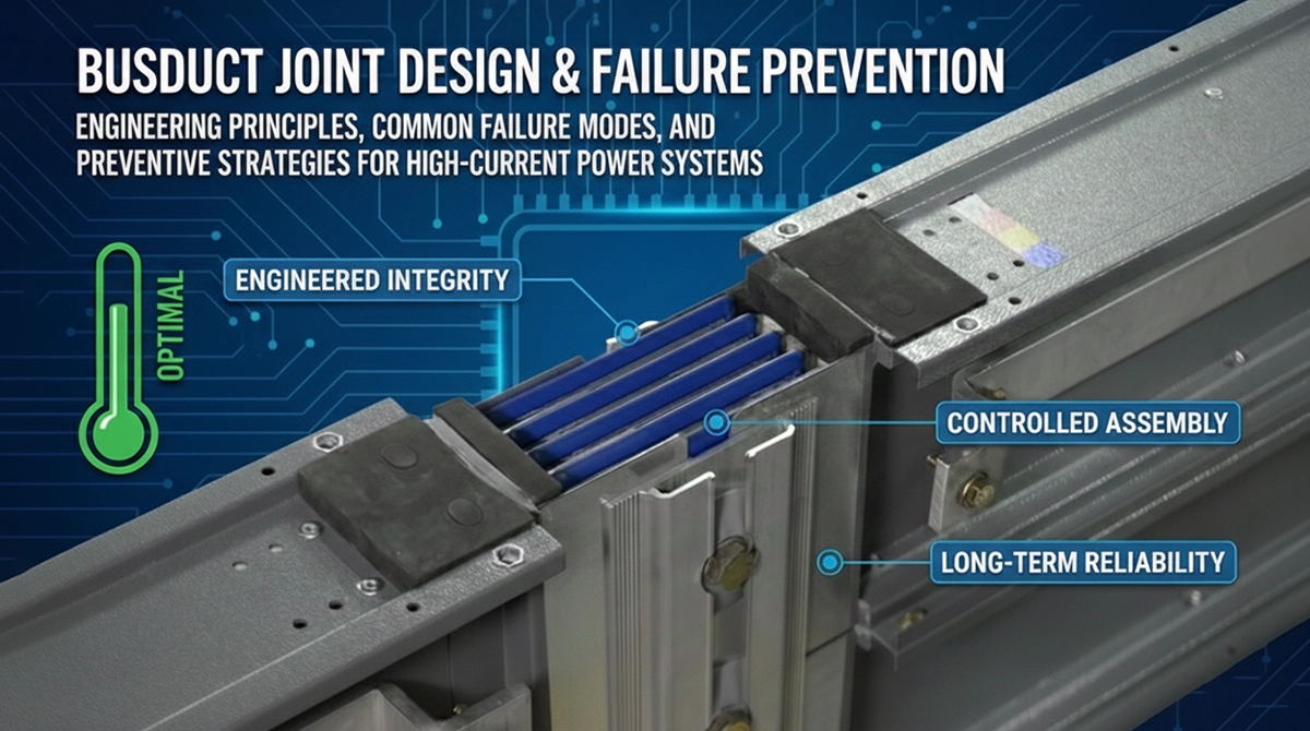
Busduct joints are the most failure-prone elements in high-current systems. This article explains joint engineering principles, failure mechanisms, and preventive strategies—covering design, assembly, testing, and installation—to ensure thermal stability and long-term reliability.
Executive Summary
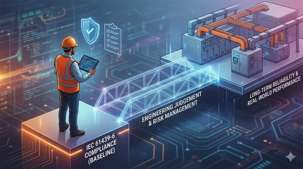
IEC 61439-6 is the governing international standard for busbar trunking systems and serves as the primary reference point for safety, performance, and verification requirements. For consulting engineers, understanding what this standard covers and, equally important, what it does not cover is critical to effective specification and risk management. While IEC 61439-6 establishes minimum acceptance criteria for busduct systems, it does not by itself guarantee long-term reliability, thermal stability, or execution predictability in real-world installations. This article explains IEC 61439-6 from a consulting engineer’s perspective, clarifying its intent, scope, limitations, and how it should be applied within a broader engineering decision framework.
1. Why Busduct Joints Deserve Special Engineering Attention
A busduct joint is the point where electrical continuity, mechanical stability, and thermal performance converge. Every current path, thermal gradient, and fault force passes through the joint.
At high current levels, even minor deviations in joint quality can result in:
- Localized overheating
- Increased contact resistance
- Accelerated insulation ageing
- Progressive failure under load cycling
Unlike conductors, joint failures often develop silently and manifest only after prolonged operation.
2. Electrical Role of a Busduct Joint
From an electrical perspective, a joint must:
- Maintain low and stable contact resistance
- Ensure uniform current distribution across phases
- Withstand transient and short-circuit currents
Any increase in contact resistance produces localized heat. Since resistive losses scale with the square of the current, joint-related heating becomes disproportionately severe at higher ratings.
3. Thermal Stress Concentration at Joint Interfaces
Joints are natural thermal bottlenecks.
Key contributors to thermal stress include:
- Imperfect surface contact
- Uneven clamping pressure
- Differential expansion between conductors
- Heat accumulation in confined joint housings
If thermal dissipation at the joint does not match that of the adjacent conductor, temperature gradients develop, accelerating degradation.
4. Mechanical Forces Acting on Busduct Joints
Busduct joints are subjected to multiple mechanical stresses:
- Static load from conductor weight
- Dynamic forces during short-circuit events
- Thermal expansion and contraction during load cycling
- Installation-induced stresses from misalignment
Joint design must ensure mechanical integrity without relying excessively on field workmanship.
5. Common Busduct Joint Failure Modes
Increased Contact Resistance
Often caused by inadequate surface preparation or inconsistent pressure, leading to heat buildup.
Loose or Uneven Fastening
Results in non-uniform current paths and localized overheating.
Insulation Breakdown
Triggered by sustained thermal stress or improper clearances at the joint interface.
Mechanical Deformation
Occurs under short-circuit forces or due to cumulative thermal cycling.
Most joint failures originate from a combination of these factors rather than a single defect.
6. Engineering Principles for Reliable Joint Design
Effective joint design incorporates:
- Precisely machined contact surfaces
- Controlled contact pressure across the joint interface
- Stable materials with compatible thermal expansion characteristics
- Insulation systems that maintain dielectric integrity under heat
- Enclosures that support heat dissipation and fault containment
Joint performance must be validated as part of the system, not assumed by design intent.
7. Importance of Controlled Assembly and Torque Management
Joint performance is highly sensitive to assembly consistency.
Critical controls include:
- Defined torque values
- Use of calibrated tools
- Repeatable assembly procedures
- Verification of mechanical alignment
Over-tightening and under-tightening are equally detrimental. Engineering-led systems eliminate guesswork at the installation stage.
8. Testing and Verification of Joint Performance
Reliable busduct systems validate joint integrity through:
- Temperature rise testing under rated current
- Short-circuit withstand testing
- Insulation resistance and dielectric tests
- Visual and dimensional inspection during routine verification
Testing confirms that joint behavior aligns with system-level performance expectations.
9. Installation Practices That Influence Joint Reliability
Even well-designed joints can fail if installation discipline is weak.
Key considerations:
- Alignment of busduct sections before jointing
- Cleanliness of contact surfaces
- Adherence to specified assembly sequence
- Environmental conditions during installation
Installation quality directly influences joint lifespan.
10. Joint Design in Relation to Expansion and Maintenance
Joint design must accommodate:
- Thermal expansion without loss of contact pressure
- Repeated load cycling
- Future system extensions or reconfiguration
Rigid designs that do not account for operational movement often fail prematurely.
11. Preventive Design and Specification Checklist
Consulting engineers and specifiers should verify:
- Joint design philosophy and materials
- Assembly torque control methodology
- Temperature rise test results including joint locations
- Short-circuit withstand ratings
- Routine inspection and verification procedures
Early scrutiny prevents latent failures.
Frequently Asked Questions
Why do most busduct failures occur at joints?
Because joints concentrate electrical, thermal, and mechanical stress in a localized area, making them more sensitive to design and assembly variations.
Can joint failures be detected early?
Thermal imaging during operation can detect abnormal heating, but preventive design is more effective than reactive monitoring.
Are factory-assembled joints more reliable than site-assembled joints?
Factory-controlled processes typically offer higher consistency, but site joints can be reliable when supported by disciplined procedures.
Does standards compliance ensure joint reliability?
Standards ensure safety thresholds, but joint reliability depends on engineering margin, testing, and installation discipline.
Should joints be maintenance-free?
Properly designed and assembled joints require minimal maintenance, but periodic inspection is recommended in critical systems.
Conclusion: Joint Integrity Determines System Integrity
In high-current power distribution systems, reliability is defined at the weakest point. Busduct joints represent the most critical interface between design intent and operational reality. Engineering-led joint design, disciplined assembly, and rigorous verification transform joints from a risk factor into a reliability asset. Treating joints as integral system components rather than accessories is essential for predictable, long-term power distribution performance.
Tags:blogs