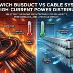
As current ratings exceed 800–1000A, cable systems face thermal and scalability limits. This article compares sandwich busducts and cables across performance, safety, scalability, and lifecycle impact, guiding engineers toward informed high-current power distribution decisions.
Executive Summary
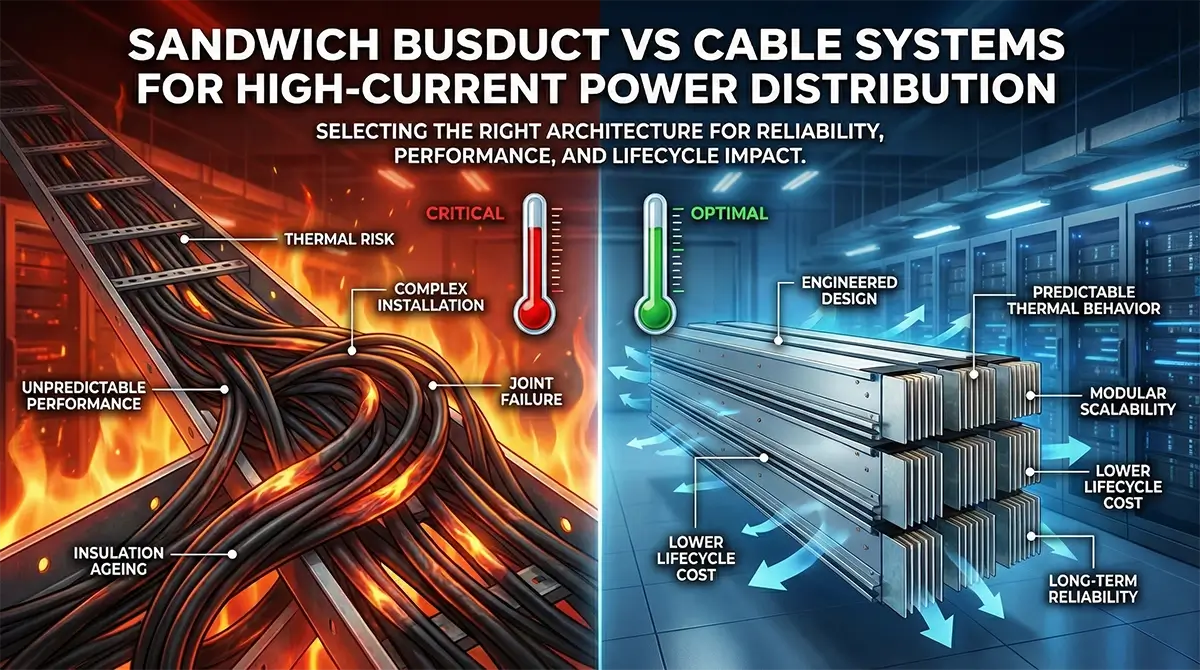
Selecting the right power distribution architecture becomes increasingly critical as current ratings rise beyond conventional thresholds. While cable systems have long been the default choice for low to moderate current applications, their limitations become evident at higher load levels, particularly above 800A–1000A. Sandwich busduct systems offer an engineered alternative designed to address thermal, electrical, mechanical, and safety challenges inherent in high-current environments. This article provides a structured comparison between sandwich busduct systems and cable-based distribution, focusing on performance, risk, scalability, and lifecycle impact to support informed engineering decisions.
1. Industry Context: Why the Comparison Matters
Modern facilities are operating under conditions that were not anticipated when many legacy power distribution practices were established. Key shifts include:
- Increasing power density in industrial and IT loads
- Vertical and space-constrained layouts
- Higher fault levels due to larger transformers
- Demand for future expansion without shutdowns
At higher current ratings, the choice between cable systems and sandwich busduct systems directly influences system reliability, safety margins, and operational predictability.
2. Overview of Cable-Based Power Distribution Systems
Cable systems distribute power using multiple insulated conductors routed through trays, ladders, or conduits. They remain widely used due to familiarity and flexibility.
Typical Characteristics
- Multiple parallel cables per phase for high current
- Dependence on installation quality and routing discipline
- Thermal performance influenced by bundling and ambient conditions
Cable systems can perform reliably when applied within their optimal operating envelope. However, challenges increase as current and system complexity grow.
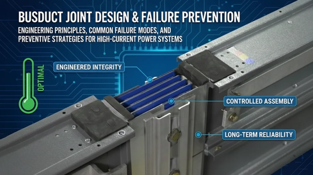
3. Overview of Sandwich Busduct Systems
Sandwich busduct systems are factory-engineered power distribution assemblies where conductors are stacked in close proximity, separated by uniform insulation, and enclosed within a rigid metallic housing.
Defining Characteristics
- Compact conductor geometry with low impedance
- Uniform insulation across conductor length
- Integrated enclosure providing mechanical protection and fault containment
- Modular construction for predictable expansion
These systems are typically deployed for current ratings from 400A up to 6300A in mission-critical applications.
4. Electrical Performance Comparison
Current Carrying Capacity
- Cable systems: Require multiple parallel runs, increasing complexity and derating considerations
- Sandwich busduct systems: Designed as a single engineered assembly with predictable current capacity
Voltage Drop
- Cable systems: Higher and less predictable due to parallel paths and joint variability
- Sandwich busduct systems: Lower impedance results in stable voltage performance
Phase Balance
- Cable systems: Susceptible to imbalance if routing or termination varies
- Sandwich busduct systems: Symmetrical conductor arrangement ensures consistent phase balance
5. Thermal Performance and Heat Dissipation
Thermal behavior is a primary differentiator at high current levels.
Cable Systems
- Heat dissipation depends on spacing, airflow, and bundling
- Derating often required in dense installations
- Hot spots may develop at terminations and joints
Sandwich Busduct Systems
- Uniform conductor spacing enables predictable temperature rise
- Enclosure aids controlled heat dissipation
- Reduced risk of localized overheating
Thermal stability directly impacts insulation life and long-term reliability.
6. Mechanical Strength and Installation Integrity
Cable Systems
- Flexible but vulnerable to movement, sagging, and installation stress
- Mechanical protection depends on tray and support quality
Sandwich Busduct Systems
- Rigid enclosure provides structural integrity
- Suitable for vertical risers and long horizontal spans
- Reduced dependency on site workmanship for mechanical stability
- Mechanical robustness becomes critical in high fault-level environments.
7. Safety and Fault Containment
Cable Systems
- Fault containment depends on routing, separation, and protective devices
- Arc fault energy may propagate along cable paths
Sandwich Busduct Systems
- Enclosure designed to withstand and contain fault energy
- Insulation and conductor spacing engineered for short-circuit stress
From a risk management perspective, sandwich busduct systems offer a more controlled fault environment.
8. Installation Time, Complexity, and Site Risk
Cable Systems
- Labour-intensive installation
- Higher risk of installation variability
- Testing and verification required for each cable run
Sandwich Busduct Systems
- Factory-assembled sections reduce site work
- Faster installation and commissioning
- Lower dependency on site-level interpretation
Reduced site complexity improves schedule predictability.
9. Scalability and Future Expansion
Cable Systems
- Expansion often requires shutdowns
- Limited flexibility once trays are congested
Sandwich Busduct Systems
- Modular tap-off units allow planned expansion
- Growth can be accommodated with minimal disruption
Scalability is a decisive factor in data centers and growing industrial facilities.
10. Lifecycle Cost Perspective
Initial material cost alone does not reflect total ownership cost.
Lifecycle Factor | Cable Systems | Sandwich Busduct Systems |
|---|---|---|
Installation time | High | Low |
Maintenance risk | Moderate | Low |
Expansion cost | High | Predictable |
Downtime impact | Significant | Minimal |
Lifecycle Factor | Cable Systems | Sandwich Busduct Systems |
Lifecycle cost analysis often favors engineered busduct systems in high-current applications.
11. Common Misapplication Risks
- Using cables beyond practical current limits
- Ignoring thermal derating in congested routes
- Underestimating joint reliability at high currents
- Selecting systems based solely on initial cost
These risks tend to surface during operation rather than commissioning.
12. Decision Framework: When to Choose Which System
Cable systems are appropriate when:
- Current levels are low to moderate
- Space is available
- Expansion is unlikely
Sandwich busduct systems are appropriate when:
- Current levels exceed 800A–1000A
- Reliability and uptime are critical
- Future expansion is expected
- Installation time and safety are priorities
Engineering context, not convention, should drive selection.
Frequently Asked Questions
Is a sandwich busduct system safer than cables?
Yes, in high-current applications, sandwich busduct systems provide better fault containment, controlled thermal behavior, and reduced arc propagation risk.
At what current level do cables become impractical?
While application-specific, cable systems typically become complex and inefficient beyond 800A–1000A.
Are sandwich busduct systems compliant with international standards?
They are designed to comply with IEC 61439-6, with performance dependent on engineering and testing discipline.
Do busduct systems require less maintenance?
Yes, due to reduced joints, controlled installation, and enclosed construction.
Which system offers better long-term scalability?
Sandwich busduct systems are better suited for planned expansion and evolving load profiles.
Conclusion: Engineering Choice, Not a Preference
The decision between sandwich busduct systems and cable-based distribution is not a matter of preference but of engineering suitability. As current levels rise and system reliability becomes non-negotiable, the structured, predictable performance of sandwich busduct systems offers clear advantages. Evaluating electrical, thermal, mechanical, and lifecycle factors holistically ensures that power distribution infrastructure supports long-term operational goals.
Tags:blogs