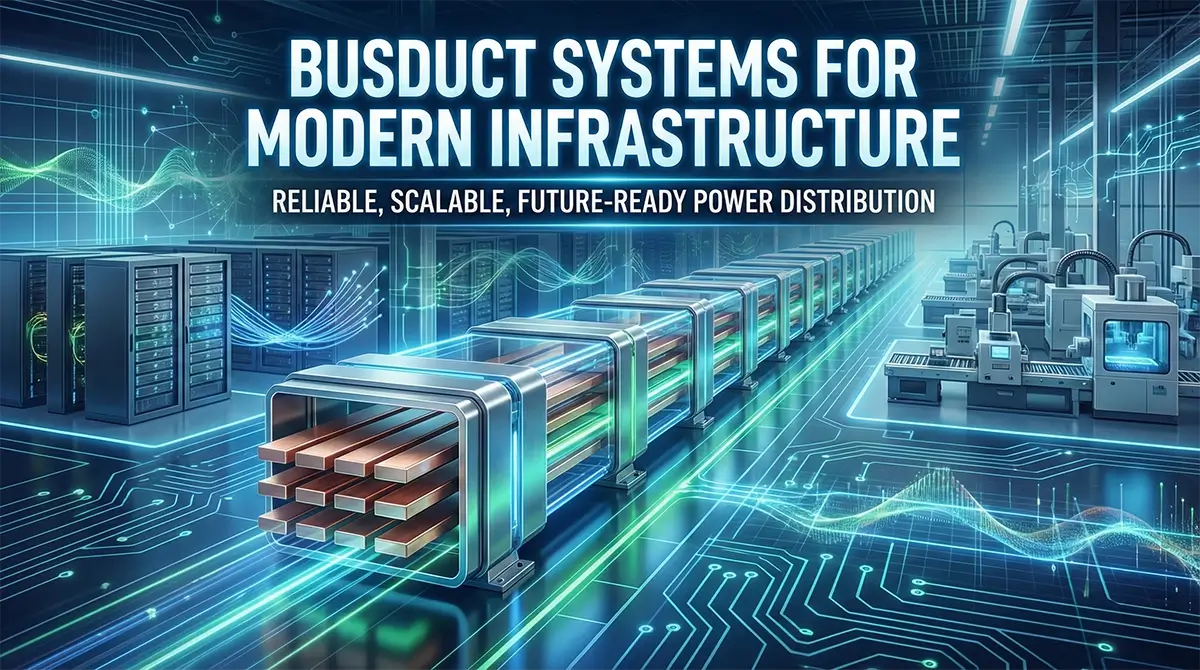
Power distribution has evolved into a mission-critical system. This article explores sandwich-type busducts, explaining fundamentals, design principles, standards, applications, and selection frameworks to help engineers specify safe, scalable, high-current power infrastructure.
Executive Summary
Power distribution is no longer a passive utility layer. In modern industrial plants, data centers, commercial complexes, and infrastructure projects, it has become a critical determinant of safety, uptime, and long-term scalability. As power densities rise and project timelines compress, traditional cable-based systems and loosely engineered busbar solutions increasingly struggle to deliver predictable performance. Busduct systems, particularly sandwich-type busduct architectures, offer a structured, standards-driven alternative designed for high-current, mission-critical applications. This pillar article provides a comprehensive engineering perspective on busduct systems, covering fundamentals, design considerations, standards, applications, and decision frameworks to support informed specification and long-term infrastructure planning.
1. The Evolving Role of Power Distribution in Modern Infrastructure
Power distribution systems today operate under significantly higher stress than in the past. Factors reshaping design priorities include:
- Increasing electrical load density
- Compact plant layouts and vertical distribution
- High fault-level environments
- Stringent safety and compliance expectations
- Demand for future expansion without downtime
In many facilities, power distribution failures result not from component defects but from systemic design limitations. As current levels increase beyond conventional thresholds, design margin, thermal stability, and fault containment become decisive factors rather than optional enhancements.
2. Limitations of Legacy Power Distribution Approaches
Cable-Based Distribution Constraints
While cable systems remain suitable for low to moderate current levels, they introduce challenges at scale:
- Derating due to cable bundling
- Uneven heat dissipation
- Large routing space requirements
- High installation and maintenance complexity
As systems approach higher current ratings, cable management becomes increasingly difficult to control and verify.
Non-Optimized Busbar Systems
Busbar solutions without compact conductor arrangement or disciplined joint engineering often suffer from:
- Magnetic imbalance
- Hot spots at joints
- Mechanical instability over long runs
- Inconsistent performance across installations
These issues typically surface during operation rather than commissioning, increasing lifecycle risk.
3. Busduct Systems Explained: Engineering Fundamentals
A busduct system is a factory-engineered power distribution assembly that integrates conductors, insulation, joints, and enclosure into a standardized modular system.
Core Functional Elements
- Conductors: Copper or aluminium sized for current capacity and fault withstand
- Insulation: Continuous, high-dielectric insulation ensuring phase separation
- Enclosure: Metallic housing providing mechanical protection and fault containment
- Joints: Engineered interfaces critical to electrical and thermal continuity
The effectiveness of a busduct system lies in how these elements are integrated rather than treated as independent components.
4. Sandwich Busduct Systems: A Structured Design Approach
Sandwich busduct systems arrange conductors in close proximity, separated by uniform insulation and enclosed within a rigid housing.
Engineering Advantages
- Lower impedance due to compact conductor geometry
- Predictable thermal behavior across the system
- Improved short-circuit withstand capability
- Reduced electromagnetic imbalance
- Compact footprint for space-constrained installations
These characteristics make sandwich busduct systems well suited for high-current distribution ranging from 400A to 6300A.
5. Electrical, Thermal, and Mechanical Performance Considerations
Electrical Performance
Key design objectives include:
- Minimal voltage drop
- Balanced phase currents
- Stable performance under transient loads
Low impedance paths directly influence system efficiency and reliability.
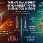
Thermal Performance
Thermal stability is determined by:
- Uniform conductor spacing
- Insulation thermal class
- Enclosure heat dissipation characteristics
Predictable temperature rise extends insulation life and reduces failure risk.
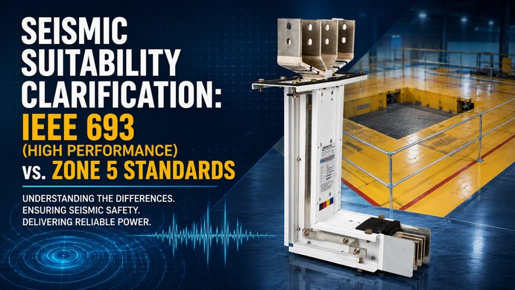
Mechanical Performance
Mechanical integrity ensures:
- Resistance to vibration and seismic loads
- Stability in vertical risers and long spans
- Protection during installation and operation
Mechanical robustness is essential for maintaining joint integrity over time.
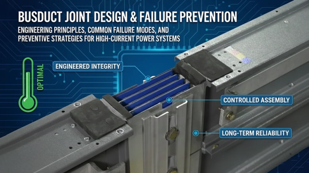
6. Safety, Fault Containment, and Risk Mitigation
High fault currents pose significant safety risks in power distribution systems. Well-engineered busduct systems address this through:
- Controlled fault current paths
- Enclosure strength for arc containment
- Insulation systems designed for fault stress
- Joint designs that prevent localized overheating
Safety is achieved through system-level engineering rather than isolated protective features.
7. Standards, Testing, and Quality Discipline
IEC 61439-6 defines performance and safety benchmarks for busbar trunking systems. However, standards represent minimum acceptance criteria rather than performance guarantees.
Beyond Compliance
Engineering-led systems emphasize:
- Routine temperature rise testing
- High-voltage withstand testing
- Insulation resistance verification
- Mechanical and dimensional consistency
Quality discipline ensures that design intent is consistently realized in manufactured systems.
8. Application-Specific Design Considerations
Industrial Facilities
- High fault levels
- Heavy-duty mechanical requirements
- Continuous operation
Design focus: thermal endurance and mechanical strength.
Data Centers
- High power density
- Redundancy and scalability
- Tight voltage tolerance
Design focus: low impedance and modular expansion.
Commercial Buildings
- Mixed load profiles
- Space optimization
- Lifecycle cost efficiency
Design focus: compact design and installation efficiency.
Infrastructure Projects
- Long distribution runs
- Regulatory oversight
- High safety expectations
Design focus: fault containment and long-term reliability.
9. Engineering-Led Manufacturing and Execution Predictability
System performance is influenced as much by manufacturing discipline as by design calculations.
Key attributes include:
- Integrated conductor fabrication and insulation
- Controlled joint assembly processes
- Standardized testing protocols
- Documentation and traceability
Engineering-led manufacturing reduces variability, improving predictability across projects.
10. Common Specification and Design Pitfalls
- Undersizing systems without accounting for future growth
- Ignoring thermal derating in compact layouts
- Treating joints as accessories rather than system-critical elements
- Prioritizing initial cost over lifecycle performance
- Overlooking installation tolerances and alignment
Avoiding these pitfalls requires early-stage engineering involvement.
11. Decision Framework for Engineers and Project Owners
A structured evaluation framework should consider:
- Reliability: Proven performance under electrical and thermal stress
- Lifecycle Cost: Installation, operation, and expansion impact
- Safety Margin: Fault containment and insulation integrity
- Vendor Capability: Engineering depth and testing discipline
- Scalability: Ability to expand without system disruption
This approach aligns technical decisions with long-term operational objectives.
12. Frequently Asked Questions
What is a busduct system?
A busduct system is a factory-engineered power distribution assembly that integrates conductors, insulation, joints, and enclosure into a modular, standardized system designed for high-current applications.
When should busduct systems be preferred over cables?
Busduct systems are preferred at higher current levels, in space-constrained environments, and where reliability, safety, and scalability are critical.
What makes sandwich busduct systems suitable for mission-critical applications?
Their compact conductor arrangement, low impedance, predictable thermal behavior, and high fault containment capability.
Is IEC 61439-6 compliance sufficient?
Compliance ensures baseline safety, but long-term reliability depends on engineering discipline, testing philosophy, and manufacturing quality.
What current ratings can busduct systems support?
Typical applications range from 400A to 6300A, depending on system design and operating conditions.
Conclusion: Built for Reliability. Engineered for Growth.
Reliable power distribution is a result of disciplined engineering, structured design, and execution predictability. Busduct systems, when engineered as integrated systems rather than assembled components, provide the foundation for safe, scalable, and future-ready infrastructure. Thoughtful specification and application-specific design ensure that power distribution systems support long-term operational goals rather than constrain them.
Tags:blogs